|
|
|
PDF ADS820U Data sheet ( Hoja de datos )
| Número de pieza | ADS820U | |
| Descripción | 10-Bit/ 20MHz Sampling ANALOG-TO-DIGITAL CONVERTER | |
| Fabricantes | Burr-Brown Corporation | |
| Logotipo | ||
Hay una vista previa y un enlace de descarga de ADS820U (archivo pdf) en la parte inferior de esta página. Total 14 Páginas | ||
|
No Preview Available !
® ADS820U
ADS820E
ADS820
TM 10-Bit, 20MHz Sampling
ANALOG-TO-DIGITAL CONVERTER
FEATURES
q NO MISSING CODES
q INTERNAL REFERENCE
q LOW DIFFERENTIAL LINEARITY ERROR:
0.2LSB
q LOW POWER: 195mW
q HIGH SNR: 60dB
q WIDEBAND TRACK/HOLD: 65MHz
q PACKAGES: 28-Pin SOIC and 28-PIN SSOP
APPLICATIONS
q SET-TOP BOXES
q CABLE MODEMS
q VIDEO DIGITIZING
q CCD IMAGING
Camcorders
Copiers
Scanners
Security Cameras
q IF AND BASEBAND DIGITIZATION
DESCRIPTION
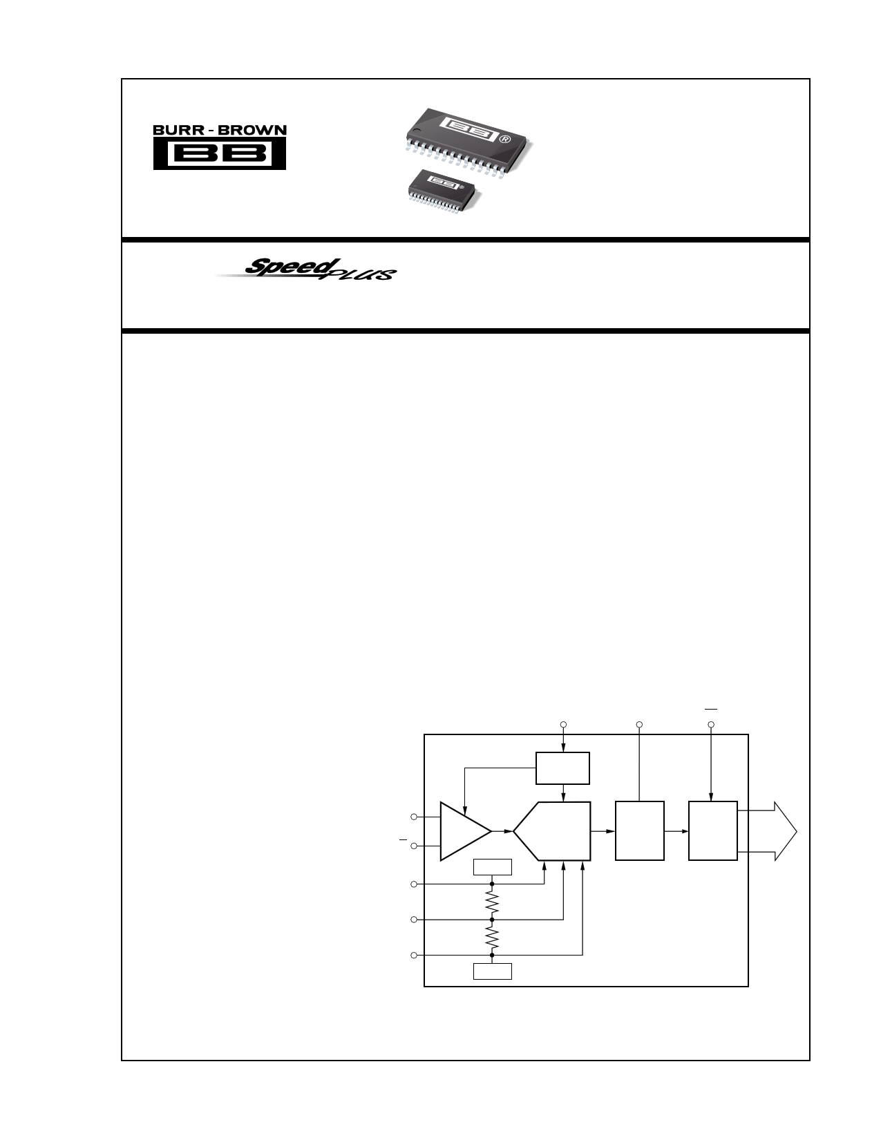
The ADS820 is a low power, monolithic 10-bit, 20MHz
analog-to-digital converter utilizing a small geometry
CMOS process. This COMPLETE converter includes
a 10-bit quantizer with internal track/hold, reference,
and a power down feature. It operates from a single
+5V power supply and can be configured to accept
either differential or single-ended input signals.
The ADS820 employs digital error correction to pro-
vide excellent Nyquist differential linearity perfor-
mance for demanding imaging applications. Its low
distortion, high SNR and high oversampling capability
give it the extra margin needed for telecommunications
and video applications.
This high performance converter is specified for AC
and DC performance at a 20MHz sampling rate. The
ADS820 is available in 28-pin SOIC and SSOP
packages.
CLK
Timing
Circuitry
MSBI
OE
IN
IN
REFT
CM
REFB
T/H
+3.25V
Pipeline
A/D
Error
Correction
Logic
3-State
Outputs
10-Bit
Digital
Data
+1.25V
International Airport Industrial Park • Mailing Address: PO Box 11400, Tucson, AZ 85734 • Street Address: 6730 S. Tucson Blvd., Tucson, AZ 85706 • Tel: (520) 746-1111 • Twx: 910-952-1111
Internet: http://www.burr-brown.com/ • FAXLine: (800) 548-6133 (US/Canada Only) • Cable: BBRCORP • Telex: 066-6491 • FAX: (520) 889-1510 • Immediate Product Info: (800) 548-6132
©1995 Burr-Brown Corporation
PDS-1288D
Printed in U.S.A. October, 1996
1 page 
TYPICAL PERFORMANCE CURVES
At TA = +25°C, VS = +5V, Sampling Rate = 20MHz, with a 50% duty cycle clock having a 2ns rise/fall time, unless otherwise noted.
0
–20
–40
–60
–80
–100
–120
0
SPECTRAL PERFORMANCE
fIN = 500kHz
fS = 10MHz
1.0 2.0 3.0 4.0
Frequency (MHz)
5.0
0
–20
–40
–60
–80
–100
–120
0
SPECTRAL PERFORMANCE
fIN = 4.8MHz
2.0 4.0 6.0 8.0
Frequency (MHz)
10.0
0
–20
–40
–60
–80
–100
–120
0
SPECTRAL PERFORMANCE
fIN = 9.8MHz
2.0 4.0 6.0 8.0
Frequency (MHz)
10.0
0
–20
–40
–60
–80
–100
–120
0.0
TWO-TONE INTERMODULATION
f1 = 4.5MHz
f2 = 4.4MHz
2.50
5.00
Frequency (MHz)
7.50
10.00
DIFFERENTIAL LINEARITY ERROR
2.0
fIN = 500kHz
1.0
0
–1.0
–2.0
24 224 424 624 824 1024
Code
DIFFERENTIAL LINEARITY ERROR
2.0
fIN = 10MHz
1.0
0
–1.0
–2.0
24 224 424 624 824 1024
Code
®
5 ADS820
5 Page 
vides good high frequency AC performance. It is important
to select a transformer that gives low distortion and does not
exhibit core saturation at full scale voltage levels. Since the
transformer does not appreciably load the ladder, there is no
need to buffer the common-mode (CM) output in this in-
stance. In general, it is advisable to keep the current draw
from the CM output pin below 0.5µA to avoid nonlinearity
in the internal reference ladder. A FET input operational
amplifier such as the OPA130 can provide a buffered refer-
ence for driving external circuitry. The analog IN and IN
inputs should be bypassed with 22pF capacitors to minimize
track/hold glitches and to improve high input frequency
performance.
Figure 5 illustrates another possible low cost interface circuit
which utilizes resistors and capacitors in place of a trans-
former. Depending on the signal bandwidth, the component
values should be carefully selected in order to maintain the
performance outlined in the data sheet. The input capacitors,
CIN, and the input resistors, RIN, create a high-pass filter with
the lower corner frequency at fC = 1/(2πRINCIN). The corner
frequency can be reduced by either increasing the value of
RIN or CIN. If the circuit operates with a 50Ω or 75Ω
impedance level, the resistors are fixed and only the value of
the capacitor can be increased. Usually AC-coupling capaci-
tors are electrolytic or tantalum capacitors with values of
1µF or higher. It should be noted that these large capacitors
become inductive with increased input frequency, which
could lead to signal amplitude errors or oscillation. To
maintain a low AC-coupling impedance throughout the sig-
nal band, a small value (e.g. 1µF) ceramic capacitor could be
added in parallel with the polarized capacitor.
Capacitors CSH1 and CSH2 are used to minimize current
glitches resulting from the switching in the input track and
hold stage and to improve signal-to-noise performance. These
capacitors can also be used to establish a low-pass filter and
effectively reduce the noise bandwidth. In order to create a
real pole, resistors RSER1 and RSER2 were added in series with
each input. The cut-off frequency of the filter is determined
by fC = 1/(2πRSER•(CSH+CADC)) where RSER is the resistor in
series with the input, CSH is the external capacitor from the
input to ground, and CADC is the internal input capacitance of
the A/D converter (typically 4pF).
Resistors R1 and R2 are used to derive the necessary common
mode voltage from the buffered top and bottom references.
The total load of the resistor string should be selected so that
the current does not exceed 1mA. Although the circuit in
Figure 5 uses two resistors of equal value so that the common
mode voltage is centered between the top and bottom refer-
ence (+2.25V), it is not necessary to do so. In all cases the
center point, VCM, should be bypassed to ground in order to
provide a low impedance AC ground.
If the signal needs to be DC coupled to the input of the
ADS820, an operational amplifier input circuit is required.
In the differential input mode, any single-ended signal must
be modified to create a differential signal. This can be
accomplished by using two operational amplifiers, one in
the noninverting mode for the input and the other amplifier
in the inverting mode for the complementary input. The low
distortion circuit in Figure 6 will provide the necessary input
shifting required for signals centered around ground. It also
employs a diode for output level shifting to guarantee a low
distortion +3.25V output swing. Another DC-coupled circuit
is shown in Figure 7. Other amplifiers can be used in place
of the OPA642s if the lowest distortion is not necessary. If
output level shifting circuits are not used, care must be taken
to select operational amplifiers that give the necessary per-
formance when swinging to +3.25V with a ±5V supply
operational amplifier. The OPA620 and OPA621, or the
lower power OPA650 and OPA651 can be used in place of
the OPA642s in Figure 6. In that configuration, the OPA650
and OPA651 will typically swing to within 100mV of
positive full scale. If the OPA621 or OPA651 is used, the
input buffer must be configured in a gain of 2.
CIN
0.1µF
RIN1
25Ω
RIN2
25Ω
CIN
0.1µF
*RSER1
49.9Ω
R3
1kΩ
C2
0.1µF
*RSER2
49.9Ω
NOTE: * indicates optional component.
R1
(6kΩ)
CSH1
22pF
VCM
C1
0.1µF
IN
+3.25V
Top Reference
ADS8xx
R2
(6kΩ)
CSH2
22pF
IN
C3
0.1µF
+1.25V
Bottom Reference
FIGURE 5. AC-Coupled Differential Input Circuit.
11
ADS820
®
11 Page | ||
| Páginas | Total 14 Páginas | |
| PDF Descargar | [ Datasheet ADS820U.PDF ] | |
Hoja de datos destacado
| Número de pieza | Descripción | Fabricantes |
| ADS820 | 10-Bit/ 20MHz Sampling ANALOG-TO-DIGITAL CONVERTER | Burr-Brown Corporation |
| ADS820 | 10-Bit 20MHz Sampling Analog-To-Digital Converter (Rev. B) | Texas Instruments |
| ADS8201 | 2.2V to 5.5V Low-Power 12-Bit 100kSPS 8-Ch Data Acq System with PGA and SPI (Rev. B) | Texas Instruments |
| ADS820E | 10-Bit/ 20MHz Sampling ANALOG-TO-DIGITAL CONVERTER | Burr-Brown Corporation |
| Número de pieza | Descripción | Fabricantes |
| SLA6805M | High Voltage 3 phase Motor Driver IC. |
Sanken |
| SDC1742 | 12- and 14-Bit Hybrid Synchro / Resolver-to-Digital Converters. |
Analog Devices |
|
DataSheet.es es una pagina web que funciona como un repositorio de manuales o hoja de datos de muchos de los productos más populares, |
| DataSheet.es | 2020 | Privacy Policy | Contacto | Buscar |