|
|
|
PDF ADS7833 Data sheet ( Hoja de datos )
| Número de pieza | ADS7833 | |
| Descripción | 10-Channel/ 12-Bit DATA ACQUISITION SYSTEM | |
| Fabricantes | Burr-Brown Corporation | |
| Logotipo | ||
Hay una vista previa y un enlace de descarga de ADS7833 (archivo pdf) en la parte inferior de esta página. Total 12 Páginas | ||
|
No Preview Available !
® ADS7833
10-Channel, 12-Bit
DATA ACQUISITION SYSTEM
FEATURES
q 3 SIMULTANEOUS SAMPLED CHANNELS
q 3 SYNCHRONIZED 12-BIT ADCs
q 6.6µs THROUGHPUT RATE
q FULLY DIFFERENTIAL MUX INPUTS
q DIGITALLY SELECTABLE INPUT RANGES
q ±5V POWER SUPPLIES
q SERIAL DIGITAL INPUT/OUTPUTS
q 2 SIMULTANEOUS SAMPLED AUXILIARY
CHANNELS
q DIRECT INTERFACE TO MOTOROLA’S
DSP56004/7
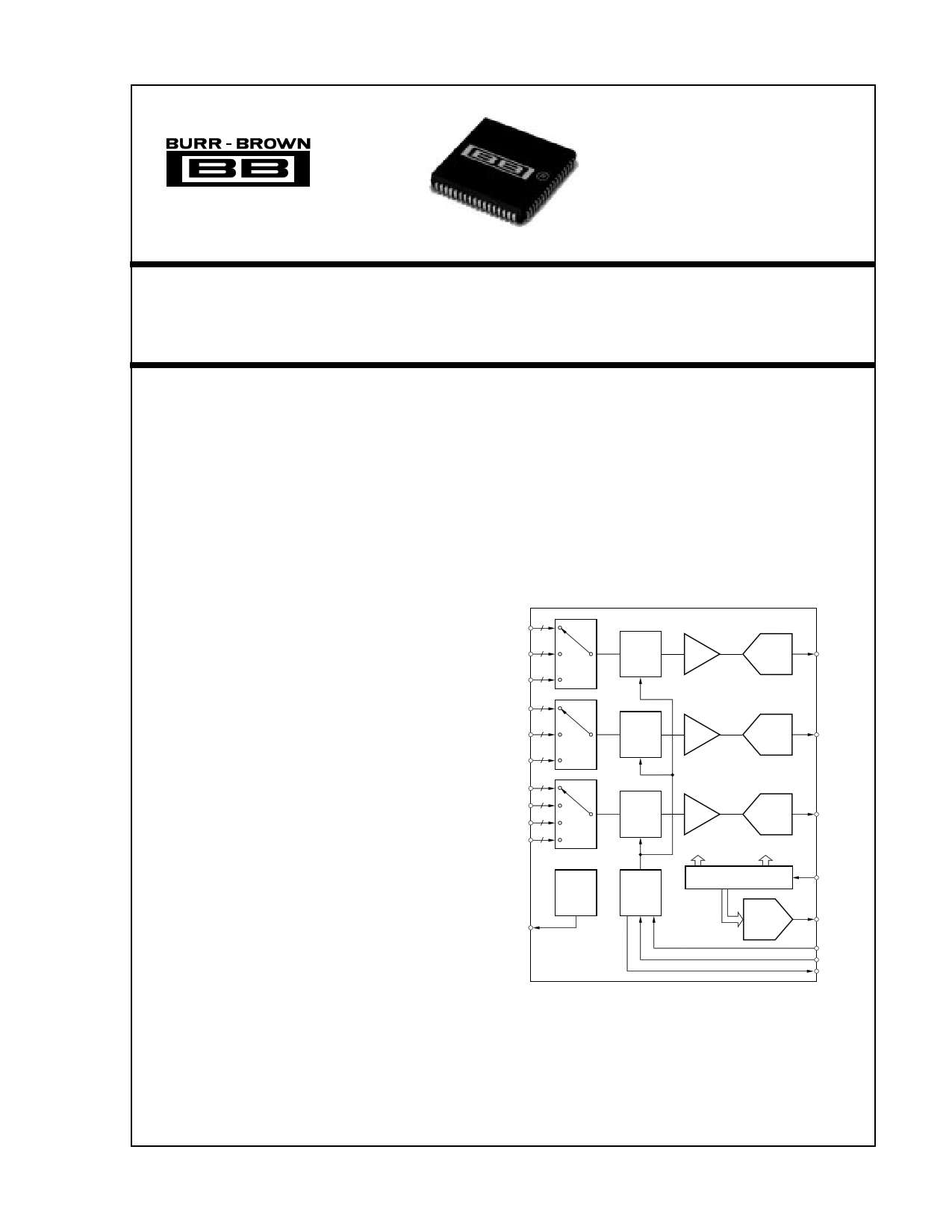
DESCRIPTION
The ADS7833 consists of three 12-bit analog-to-digi-
tal converters preceded by three simultaneously oper-
ating sample-hold amplifiers, and multiplexers for 10
differential inputs. The ADCs have simultaneous se-
rial outputs for high speed data transfer and data
processing.
The ADS7833 also offers a programmable gain ampli-
fier with programmable gains of 1.0V/V, 1.25V/V,
2.5V/V, and 5.0V/V. Channel selection and gain se-
lection are selectable through the serial input control
word. The high through put rate is maintained by
simultaneously clocking in the 13-bit input control
word for the next conversion while the present conver-
sions are clocked out.
The part also contains an 8-bit digital-to-analog con-
verter whose digital input is supplied as part of the
input control word.
APPLICATIONS
q AC MOTOR SPEED CONTROLS
q THREE PHASE POWER CONTROL
q UNINTERRUPTABLE POWER SUPPLIES
q VIBRATION ANALYSIS
q PC DATA ACQUISITION
q MEDICAL INSTRUMENTATION
V1-1
V1-2
V1-3
V2-1
V2-2
V2-3
V3-1
V3-2
V3-3
V3-4
2
2
2
2
2
2
2
2
2
2
MUX1
MUX2
MUX3
CAP
2.5V
Ref
SH1 PGA1
ADC1
12-Bit
Serial Out1
SH2 PGA2
ADC2
12-Bit
Serial Out2
SH3 PGA3
ADC3
12-Bit
Control
Logic
Input Select
Gain Select
Input Setup
Register
DAC
DAC
8-Bit
Serial Out3
Serial IN
Voltage Out
Clock
Convert
Busy
International Airport Industrial Park • Mailing Address: PO Box 11400, Tucson, AZ 85734 • Street Address: 6730 S. Tucson Blvd., Tucson, AZ 85706 • Tel: (520) 746-1111 • Twx: 910-952-1111
Internet: http://www.burr-brown.com/ • FAXLine: (800) 548-6133 (US/Canada Only) • Cable: BBRCORP • Telex: 066-6491 • FAX: (520) 889-1510 • Immediate Product Info: (800) 548-6132
©1994 Burr-Brown Corporation
PDS-11235C
ADPrSinte7d8in3U3.S.A. May, 1997
®
1 page 
TYPICAL PERFORMANCE CURVES
At VANA+ = +5V, VANA– = –5V, VDIG+ = +5V, VDIG– = –5V and TA = 25°C, using internal reference, fCLOCK = 2.1MHz.
OFFSET vs TEMPERATURE
1.4
1.2
1.0
0.8
0.6
0.4
0.2
0
–55 –40 –25
0
25 70
Temperature (°C)
85 125
0.9
0.8
0.7
0.6
0.5
0.4
0.3
0.2
0.1
0
–55
FULL SCALE vs TEMPERATURE
–40 –25
0
25 70
Temperature (°C)
85
125
DIFFERENTIAL LINEARITY (MIN) vs TEMPERATURE
0.000
–0.100
–0.200
–0.300
–0.400
–0.500
–0.600
–0.700
–55 –40 –25
0
25 70
Temperature (°C)
85 125
DIFFERENTIAL LINEARITY (MAX) vs TEMPERATURE
0.40
0.35
0.30
0.25
0.20
0.15
0.10
0.05
0
–55 –40 –25
0
25 70
Temperature (°C)
85 125
0.000
INTEGRAL LINEARITY (MIN) vs TEMPERATURE
–0.050
–0.100
–0.150
–0.200
–0.250
–0.300
–0.350
–0.400
–0.450
–55 –40 –25
0
25 70
Temperature (°C)
85 125
INTEGRAL LINEARITY (MAX) vs TEMPERATURE
0.45
0.40
0.35
0.30
0.25
0.20
0.15
0.10
0.05
0
–55 –40 –25
0
25 70
Temperature (°C)
85 125
®
5 ADS7833
5 Page 
MICROPROCESSOR INTERFACE
The internal logic of the ADS7833 is designed for easy
control and data interface with microprocessors. Figure 4
shows the interface for loading the input control word from
the microprocessor data bus into the serial input of the
ADS7833.
Table VIII provides a sample assembly code and Figure 4
shows the connection diagram for connecting an ADS7833
to the DSP56004N—or DSP56007 a Motorola Digital Sig-
nal Processor. This configuration allows for full control of
the ADS7833 as well as receiving all three conversion
results simultaneously. The start of conversion is generated
by the DSP56004 as well as the sample time of the asynchro-
nous sample/holds.
DSP56004/7
SDO0
SDO1
SOI0
SOI1
MOSI/HA0
MISO/NAU
SCKT
SCKR
SCK/SCL
WST
WSR
SS/HA2
SDO2
(optional)
ADS7833
CONV
SERIN
SOUT1
SOUT2
SOUT3
ASH
CLK
V1-1
V1-2
V1-3
V2-1
V2-2
V2-3
V3-1
V3-2
V3-3
V3-4
AOUT
While this is one of the most useful, the DSP56004/7 is
flexible enough to allow various other configurations. These
will free up the serial outputs for use with other serial
peripherals, such as DACs.
TYPICAL ISOLATED ANALOG INPUT
Figure 5 shows an ISO130 used to isolate the current
measurement in a motor speed control application. This
amplifier is well suited for this application because of its
high transient immunity (l0kV/µs). Its differential output
feature is well suited to the differential input of the ADS7833.
Keeping the signal transmission differential helps to pre-
serve the high frequency noise rejection of the system.
A unique characteristic of the ISO130 is that it has a common
mode output voltage of approximately 2.39V. To accept this
level of CMV, the ADS7833 must be operated at a gain of
5V/V (±0.5V full scale differential input). (See Figure 3 and
Table VII). Since the ISO130 has a gain of 8V/V, the
maximum value of VSENSE is 62.5mV. Thus, the value of
RSENSE is chosen to scale VSENSE to this maximum value.
POWER-UP INITIALIZATION
When power is applied to the ADS7833, two conversion
cycles are required for initialization and valid digital data is
transmitted on the third cycle.
The first conversion after power is applied is performed with
indeterminate configuration values in the double buffer
output of the Input Setup Register. The second conversion
cycle loads the desired values into the register. The third
conversion uses those values to perform proper conversions
and output valid digital data from each of the ADCs.
FIGURE 4. Microprocessor Interface for Motorola
DSP56004/7.
movep
movep
movep
;
movep
movep
movep
movep
movep
#>$0,x:$ffe4
#>$0,x:$ffe1
#>$0,x:$fff1
; Disable SAI transmit port
; Disable SAI receive port
; Disable SHI port
#>$dfff00,x:$ffe5
#>$101f00,x:$ffe6
#>$0,x:$ffe7
#>$10d,x:$ffe0
#>$3,x:$ffe1
; Convert command
; DAC to midscale, G=1V/V, Channel 1 all ADCs
; For SS pin—enables SHI at proper time
; Divide by 1 pre, divide by 13—96kHz conv @ 40MHz
; Enable SAI recv (rsng edge, MSB 1st, 16-bits, slave)
wait
data
movep
movep
movep
;
btst
jcs
btst
jcc
movep
move
movep
move
move
movep
#>$2001,x:$fff0
#>$5,x:$fff1
#>$f,x:$ffe4
#14,x:$ffe1
data
#15,x:$ffe1
wait
x:$ffe2,x0
x0,x:$00
x:$ffe3,x0
x0,x:$01
x:$fff3,x0
x0,x:$02
; Set narrow spike filter, CPOL=0, CPHA=1
; Enable SHI (slave, no fifo, 16-bits)
; Enable SAI trans (rsng edge, MSB 1st, 16-bits, mstr)
; Look for a receive flag (left or right)
; Get Sout1
; Save it
; Get Sout2
; Save it
; Get Sout3
; Save it
TABLE VIII. Sample Code for Motorola DSP56004/7.
11 ADS7833
®
11 Page | ||
| Páginas | Total 12 Páginas | |
| PDF Descargar | [ Datasheet ADS7833.PDF ] | |
Hoja de datos destacado
| Número de pieza | Descripción | Fabricantes |
| ADS7830 | 8-Bit/ 8-Channel Sampling ANALOG-TO-DIGITAL CONVERTER with I2C Interface | Burr-Brown Corporation |
| ADS7830 | 8-Bit 8-Channel Sampling Analog-to-Digital Converter with I C Interface (Rev. C) | Texas Instruments |
| ADS7830I | 8-Bit/ 8-Channel Sampling ANALOG-TO-DIGITAL CONVERTER with I2C Interface | Burr-Brown Corporation |
| ADS7830IPWR | 8-Bit/ 8-Channel Sampling ANALOG-TO-DIGITAL CONVERTER with I2C Interface | Burr-Brown Corporation |
| Número de pieza | Descripción | Fabricantes |
| SLA6805M | High Voltage 3 phase Motor Driver IC. |
Sanken |
| SDC1742 | 12- and 14-Bit Hybrid Synchro / Resolver-to-Digital Converters. |
Analog Devices |
|
DataSheet.es es una pagina web que funciona como un repositorio de manuales o hoja de datos de muchos de los productos más populares, |
| DataSheet.es | 2020 | Privacy Policy | Contacto | Buscar |