|
|
|
PDF ADS7800AH Data sheet ( Hoja de datos )
| Número de pieza | ADS7800AH | |
| Descripción | 12-Bit 3ms Sampling ANALOG-TO-DIGITAL CONVERTER | |
| Fabricantes | Burr-Brown Corporation | |
| Logotipo | ||
Hay una vista previa y un enlace de descarga de ADS7800AH (archivo pdf) en la parte inferior de esta página. Total 12 Páginas | ||
|
No Preview Available !
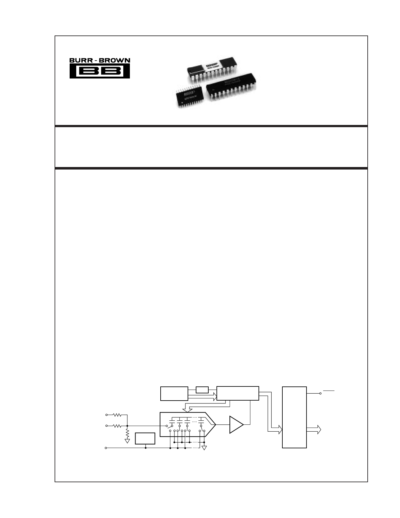
® ADS7800
12-Bit 3µs Sampling
ANALOG-TO-DIGITAL CONVERTER
FEATURES
q 333k SAMPLES PER SECOND
q STANDARD ±10V AND ±5V INPUT
RANGES
q DC PERFORMANCE OVER TEMP:
No Missing Codes
1/2LSB Integral Linearity Error
3/4LSB Differential Linearity Error
q AC PERFORMANCE OVER TEMP:
72dB Signal-to-Noise Ratio
80dB Spurious-free Dynamic Range
–80dB Total Harmonic Distortion
q INTERNAL SAMPLE/HOLD, REFERENCE,
CLOCK, AND 3-STATE OUTPUTS
q POWER DISSIPATION: 215mW max
q PACKAGE: 24-Pin Single-wide DIP
24-Lead SOIC
DESCRIPTION
The ADS7800 is a complete 12-bit sampling analog-
to-digital converter using state-of-the-art CMOS struc-
tures. It contains a complete 12-bit successive ap-
proximation A/D converter with internal sample/hold,
reference, clock, digital interface for microprocessor
control, and three-state output drivers.
The ADS7800 is specified at a 333kHz sampling rate.
Conversion time is factory set for 2.70µs max over
temperature, and the high speed sampling input stage
insures a total acquisition and conversion time of 3µs
max over temperature. Precision, laser-trimmed scal-
ing resistors provide industry-standard input ranges of
±5V or ±10V.
AC and DC performance are completely specified.
Two grades based on linearity and dynamic perform-
ance are available to provide the optimum price/
performance fit in a wide range of applications.
The 24-pin ADS7800 is available in plastic and side-
braze hermetic 0.3" wide DIPs, and in an SOIC
package. It operates from a +5V supply and either a
–12V or –15V supply. The ADS7800 is available in
grades specified over 0°C to +70°C and –40°C to
+85°C temperature ranges.
±10VIN
±5VIN
2V
Reference
Out
Control
Logic
Clock
CDAC
SAR
Internal
Ref
Comparator
Output
Latches
And
Three
State
Drivers
BUSY
Three
State
Parallel
Output
Data
Bus
International Airport Industrial Park • Mailing Address: PO Box 11400, Tucson, AZ 85734 • Street Address: 6730 S. Tucson Blvd., Tucson, AZ 85706 • Tel: (520) 746-1111 • Twx: 910-952-1111
Internet: http://www.burr-brown.com/ • FAXLine: (800) 548-6133 (US/Canada Only) • Cable: BBRCORP • Telex: 066-6491 • FAX: (520) 889-1510 • Immediate Product Info: (800) 548-6132
© 1989 Burr-Brown Corporation
PDS-1018E
Printed in U.S.A. October, 1993
1 page 
TYPICAL PERFORMANCE CURVES
At +VS = +5V, –VS = –15V, and TA = +25°C, unless otherwise noted. All plots use 1024 point FFTs.
0
–20
–40
–60
–80
–100
–120
0
FREQUENCY SPECTRUM (10kHz fIN )
fIN = 10kHz
f = 330kHz
SAMPLING
TA = 25°C
50 100
Frequency (kHz)
150 165
0
–20
–40
–60
–80
–100
–120
0
FREQUENCY SPECTRUM (50kHz fIN )
fIN = 50kHz
f = 330kHz
SAMPLING
TA = 25°C
50 100
Frequency (kHz)
150 165
SIGNAL/(NOISE + DISTORTION) vs
INPUT FREQUENCY AND AMBIENT TEMPERATURE
75
–55°C
70
65
1
10
Input Frequency (kHz)
50
150
SPURIOUS FREE DYNAMIC RANGE vs
INPUT FREQUENCY AND AMBIENT TEMPERATURE
95
90
85
80 –55°C
75 ++12255°°CC
70
65
1
10
Input Frequency (kHz)
50
150
80
60
40
20
0
1
SIGNAL/(NOISE + DISTORTION) vs
FREQUENCY AND AMPLITUDE
0dB
–20dB
–40dB
–60dB
10
Input Frequency (kHz)
50
150
SPURIOUS FREE DYNAMIC RANGE vs
INPUT FREQUENCY AND NEGATIVE SUPPLY VOLTAGE
95
90
–VS = –15V
85 –VS = –12V
80
75
70
65
1
10
Input Frequency (kHz)
50
150
®
5 ADS7800
5 Page 
converter if at all possible. A ground plane is usually the best
solution for preserving dynamic performance and reducing
noise coupling into sensitive converter circuits. Where any
compromises must be made, the common return of the
analog input signal should be referenced to pin 4, AGND,
on the ADS7800, which prevents any voltage drops that
might occur in the power supply common returns from
appearing in series with the input signal.
Coupling between analog input and digital lines should be
minimized by careful layout. For instance, if the lines must
cross, they should do so at right angles. Parallel analog and
digital lines should be separated from each other by a pattern
connected to common.
If external full scale and offset potentiometers are used, the
potentiometers and related resistors should be located as
close to the ADS7800 as possible.
CS
R/C
HBE
BUSY
DB11-DB0
tDD
FIGURE 9. Read Cycle Timing.
tDB
Data Valid
tHL & tHDR
REFERENCE BYPASS
Pin 3 (REF) should be bypassed with a 22µF to 47µF
tantalum capacitor. A rated working voltage of 2V or more
is acceptable here. This pin is used to enhance the system
accuracy of the internal reference circuit, and is not
recommended for driving external signals. If there are
important system reasons for using the ADS7800 reference
externally, the output of pin 3 must be appropriately
buffered.
“HOT SOCKET” PRECAUTION
Two separate +5V VS pins, 23 and 24, are used to minimize
noise caused by digital transients. If one pin is powered and
the other is not, the ADS7800 may “Latch Up” and draw
excessive current. In normal operation, this is not a problem
because both pins will be soldered together. However,
during evaluation, incoming inspection, repair, etc., where
the potential of a “Hot Socket” exists, care should be taken
to power the ADS7800 only after it has been socketed.
External
Gain Adjust
±10V
Input
R2
100Ω
Bipolar
Zero
Adjust
+5V
R1
10kΩ
6.65kΩ
–15V
10k
49.9Ω
1
2
3
4
5
6
7
ADS7800
FIGURE 10. ±10V Range With External Trims.
MINIMIZING “GLITCHES”
Coupling of external transients into an A/D converter can
cause errors which are difficult to debug. In addition to the
discussions earlier on layout considerations for supplies,
bypassing and grounding, there are several other useful
steps that can be taken to get the best analog performance
out of a system using the ADS7800. These potential system
problem sources are particularly important to consider when
developing a new system, and looking for the causes of
errors in breadboards.
First, care should be taken to avoid glitches during critical
times in the sampling and conversion process. Since the
ADS7800 has an internal sample/hold function, the signal
that puts it into the hold state (R/C going LOW) is critical, as
it would be on any sample/hold amplifier. The R/C falling
edge should be sharp and have minimal ringing, especially
during the 20ns after it falls.
Although not normally required, it is also good practice to
avoid glitching the ADS7800 while bit decisions are being
made. Since the above discussion calls for a fast, clean rise
and fall on R/C, it makes sense to keep the rising edge of the
convert pulse outside the time when bit decisions are being
made. In other words, the convert pulse should either be
short (under 100ns so that it transitions before the MSB
decision), or relatively long (over 2.75µs to transition after
the LSB decision).
External
Gain Adjust
Bipolar
Zero
Adjust
±5V
Input
R2
100Ω
+5V
R1
10kΩ
10kΩ
30.1kΩ
–15V
301Ω
1
2
3
4
5
6
7
ADS7800
FIGURE 11. ±5V Range With External Trims.
®
11 ADS7800
11 Page | ||
| Páginas | Total 12 Páginas | |
| PDF Descargar | [ Datasheet ADS7800AH.PDF ] | |
Hoja de datos destacado
| Número de pieza | Descripción | Fabricantes |
| ADS7800AH | 12-Bit 3ms Sampling ANALOG-TO-DIGITAL CONVERTER | Burr-Brown Corporation |
| Número de pieza | Descripción | Fabricantes |
| SLA6805M | High Voltage 3 phase Motor Driver IC. |
Sanken |
| SDC1742 | 12- and 14-Bit Hybrid Synchro / Resolver-to-Digital Converters. |
Analog Devices |
|
DataSheet.es es una pagina web que funciona como un repositorio de manuales o hoja de datos de muchos de los productos más populares, |
| DataSheet.es | 2020 | Privacy Policy | Contacto | Buscar |