|
|
|
PDF ADS1211P Data sheet ( Hoja de datos )
| Número de pieza | ADS1211P | |
| Descripción | 24-Bit ANALOG-TO-DIGITAL CONVERTER | |
| Fabricantes | Burr-Brown Corporation | |
| Logotipo | ||
Hay una vista previa y un enlace de descarga de ADS1211P (archivo pdf) en la parte inferior de esta página. Total 30 Páginas | ||
|
No Preview Available !
® ADS1210
ADS1211
ADS1210
ADS1211
ADS1211
ADS1210
ADS1211
24-Bit ANALOG-TO-DIGITAL CONVERTER
FEATURES
q DELTA-SIGMA A/D CONVERTER
q 23 BITS EFFECTIVE RESOLUTION AT 10Hz
AND 20 BITS AT 1000Hz
q DIFFERENTIAL INPUTS
q PROGRAMMABLE GAIN AMPLIFIER
q FLEXIBLE SPI COMPATIBLE SSI
INTERFACE WITH 2-WIRE MODE
q PROGRAMMABLE CUT-OFF FREQUENCY
UP TO 15.6kHz
q INTERNAL/EXTERNAL REFERENCE
q ON CHIP SELF-CALIBRATION
q ADS1211 INCLUDES 4 CHANNEL MUX
APPLICATIONS
q INDUSTRIAL PROCESS CONTROL
q INSTRUMENTATION
q BLOOD ANALYSIS
q SMART TRANSMITTERS
q PORTABLE INSTRUMENTS
q WEIGH SCALES
q PRESSURE TRANSDUCERS
DESCRIPTION
The ADS1210 and ADS1211 are precision, wide
dynamic range, delta-sigma analog-to-digital converters
with 24-bit resolution operating from a single +5V
supply. The differential inputs are ideal for direct
connection to transducers or low level voltage sig-
nals. The delta-sigma architecture is used for wide
dynamic range and to guarantee 22 bits of no missing
code performance. An effective resolution of 23 bits
is achieved through the use of a very low-noise input
amplifier at conversion rates up to 10Hz. Effective
resolutions of 20 bits can be maintained up to a
sample rate of 1kHz through the use of the unique
Turbo modulator mode of operation. The dynamic
range of the converters is further increased by provid-
ing a low-noise programmable gain amplifier with a
gain range of 1 to 16 in binary steps.
The ADS1210 and ADS1211 are designed for high
resolution measurement applications in smart trans-
mitters, industrial process control, weigh scales, chro-
matography and portable instrumentation. Both con-
verters include a flexible synchronous serial interface
which is SPI compatible and also offers a two-wire
control mode for low cost isolation.
The ADS1210 is a single channel converter and is
offered in both 18-pin DIP and 18-lead SOIC pack-
ages. The ADS1211 includes a 4 channel input multi-
plexer and is available in 24-pin DIP, 24-lead SOIC,
and 28-lead SSOP packages.
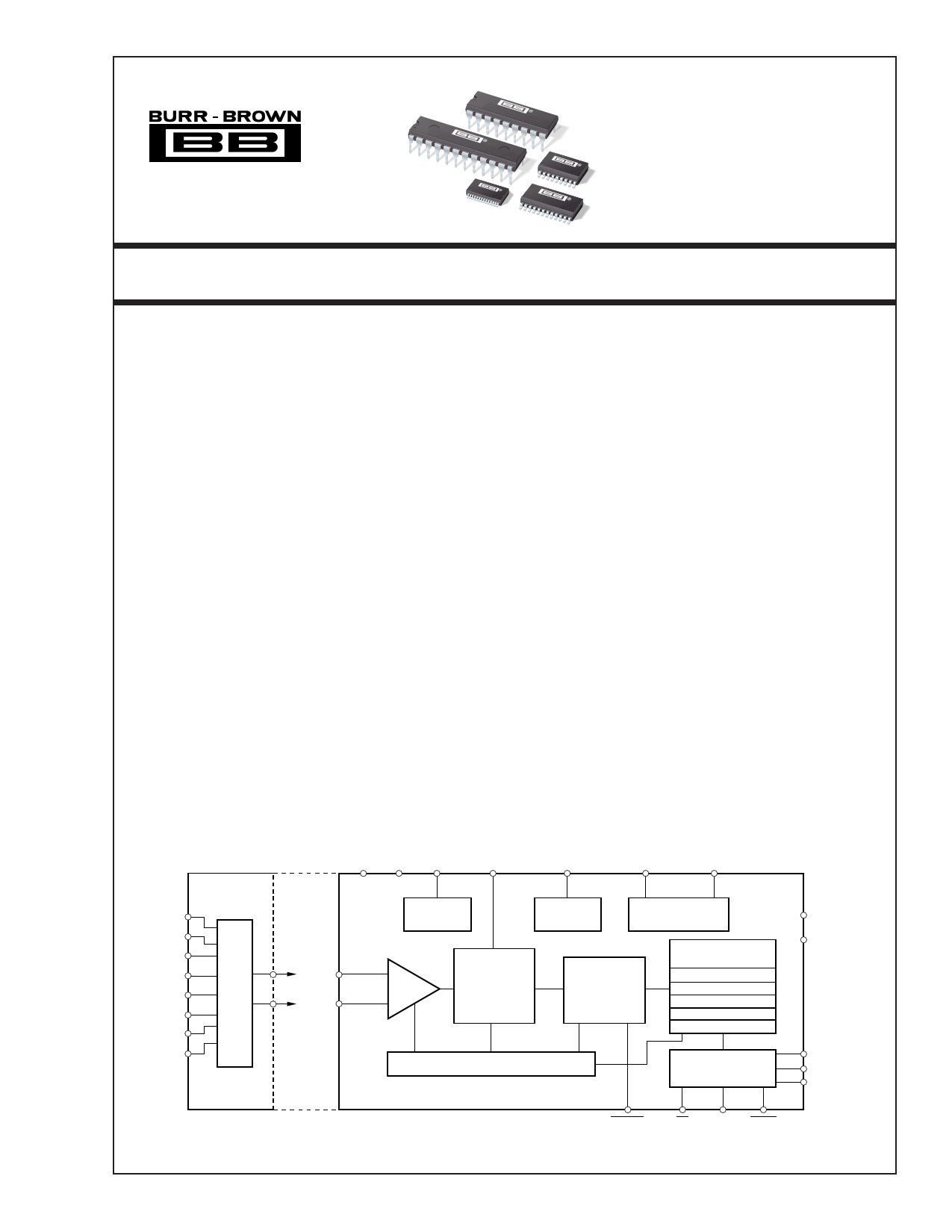
AGND AVDD REFOUT
REFIN
VBIAS
XIN XOUT
AIN1P
AIN1N
AIN2P
AIN2N
AIN3P
AIN3N
AIN4P
AIN4N
MUX
AINP
AINN
+2.5V
Reference
+3.3V Bias
Generator
Clock Generator
PGA
Second-Order
∆∑
Modulator
Third-Order
Digital Filter
Micro Controller
Instruction Register
Command Register
Data Output Register
Offset Register
Full-Scale Register
Modulator Control
Serial Interface
DGND
DVDD
SCLK
SDIO
SDOUT
ADS1211 Only
ADS1210/11
DSYNC
CS MODE DRDY
International Airport Industrial Park • Mailing Address: PO Box 11400, Tucson, AZ 85734 • Street Address: 6730 S. Tucson Blvd., Tucson, AZ 85706 • Tel: (520) 746-1111
Twx: 910-952-1111 • Internet: http://www.burr-brown.com/ • Cable: BBRCORP • Telex: 066-6491 • FAX: (520) 889-1510 • Immediate Product Info: (800) 548-6132
©1996 Burr-Brown Corporation
PDS1-1284E
ADS1210Pr,int1ed2in1U1.S.A. May, 2000
®
1 page 
ADS1211 SIMPLIFIED BLOCK DIAGRAM
AIN1P
AIN1N
AIN2P
AIN2N
AIN3P
AIN3N
AIN4P
AIN4N
4
5
2
3
24
1
22
23
AGND AVDD
6 19
REFOUT
20
REFIN
21
VBIAS
7
XIN
10
XOUT
11
MUX
+2.5V
Reference
+3.3V Bias
Generator
Clock Generator
PGA
Second-Order
∆∑
Modulator
Third-Order
Digital Filter
Micro Controller
Instruction Register
Command Register
Data Output Register
Offset Register
Full-Scale Register
12 DGND
13 DVDD
Modulator Control
Serial Interface
14
15 SCLK
16 SDIO
SDOUT
9 8 18 17
DSYNC
CS MODE DRDY
ADS1211P AND ADS1211U PIN CONFIGURATION
TOP VIEW
DIP/SOIC
AIN3N 1
AIN2P 2
AIN2N 3
AIN1P 4
AIN1N 5
AGND 6
VBIAS 7
CS 8
DSYNC 9
XIN 10
XOUT 11
DGND 12
ADS1211P
ADS1211U
24 AIN3P
23 AIN4N
22 AIN4P
21 REFIN
20 REFOUT
19 AVDD
18 MODE
17 DRDY
16 SDOUT
15 SDIO
14 SCLK
13 DVDD
ADS1211P AND ADS1211U PIN DEFINITIONS
PIN NO
1
2
3
4
5
6
7
8
9
10
11
12
13
14
15
NAME
AIN3N
AIN2P
AIN2N
AIN1P
AIN1N
AGND
VBIAS
CS
DSYNC
XIN
XOUT
DGND
DVDD
SCLK
SDIO
16 SDOUT
17 DRDY
18 MODE
19 AVDD
20 REFOUT
21 REFIN
22 AIN4P
23 AIN4N
24 AIN3P
DESCRIPTION
Inverting Input Channel 3.
Noninverting Input Channel 2.
Inverting Input Channel 2.
Noninverting Input Channel 1.
Inverting Input Channel 1.
Analog Ground.
Bias Voltage Output, +3.3V nominal.
Chip Select Input.
Control Input to Synchronize Serial Output Data.
System Clock Input.
System Clock Output (for Crystal or Resonator).
Digital Ground.
Digital Supply, +5V nominal.
Clock Input/Output for serial data transfer.
Serial Data Input (can also function as Serial Data
Output).
Serial Data Output.
Data Ready.
SCLK Control Input (Master = 1, Slave = 0).
Analog Supply, +5V nominal.
Reference Output: +2.5V nominal.
Reference Input.
Noninverting Input Channel 4.
Inverting Input Channel 4.
Noninverting Input Channel 3.
®
5 ADS1210, 1211
5 Page 
fXIN—The frequency of the crystal oscillator or CMOS
compatible input signal at the XIN input of the ADS1210/11.
fMOD—The frequency or speed at which the modulator of the
ADS1210/11 is running, given by the following equation:
f MOD
=
f XIN
• Turbo
512
Mode
fSAMP—The frequency or switching speed of the input
sampling capacitor. The value is given by the following
equation:
f SAMP
=
f XIN
•
Turbo
Mode
512
•
Gain
Setting
fDATA, tDATA—The frequency of the digital output data
produced by the ADS1210/11 or the inverse of this (the
period), respectively, fDATA is also referred to as the data rate.
f DATA
=
f XIN • Turbo Mode
512 • (Decimation Ratio + 1)
,
t DATA =
1
f DATA
Conversion Cycle—The term “conversion cycle” usually
refers to a discrete A/D conversion operation, such as that
performed by a successive approximation converter. As
used here, a conversion cycle refers to the tDATA time period.
However, each digital output is actually based on the modu-
lator results from the last three tDATA time periods.
DIGITAL FILTER
The digital filter of the ADS1210/11 computes the output
result based on the most recent results from the delta-sigma
modulator. The number of modulator results that are used
depend on the decimation ratio set in the Command Regis-
ter. At the most basic level, the digital filter can be thought
of as simply averaging the modulator results and presenting
this average as the digital output.
While the decimation ratio determines the number of modu-
lator results to use, the modulator runs faster at higher Turbo
Modes. These two items, together with the ADS1210/11
clock frequency, determine the output data rate:
f DATA
=
f XIN • Turbo Mode
512 • (Decimation Ratio
+ 1)
Also, since the conversion result is essentially an average,
the data rate determines where the resulting notches are in
the digital filter. For example, if the output data rate is 1kHz,
then a 1kHz input frequency will average to zero during the
1ms conversion cycle. Likewise, a 2kHz input frequency
will average to zero, etc.
In this manner, the data rate can be used to set specific notch
frequencies in the digital filter response (see Figure 1 for the
normalized response of the digital filter). For example, if the
rejection of power line frequencies is desired, then the data
rate can simply be set to the power line frequency. Figures
2 and 3 show the digital filter response for a data rate of
50Hz and 60Hz, respectively.
0
–20
–40
–60
–80
–100
–120
–140
–160
0
NORMALIZED DIGITAL FILTER RESPONSE
1 234 5
Frequency (Hz)
FIGURE 1. Normalized Digital Filter Response.
6
0
–20
–40
–60
–80
–100
–120
–140
–160
0
–40
–60
–80
–100
–120
–140
–160
45
50
46 47
FILTER RESPONSE
100 150 200
Frequency (Hz)
FILTER RESPONSE
48 49 50 51 52
Frequency (Hz)
250 300
53 54 55
FIGURE 2. Digital Filter Response at a Data Rate of 50Hz.
0
–20
–40
–60
–80
–100
–120
–140
–160
0
FILTER RESPONSE
50 100 150 200 250 300
Frequency (Hz)
FILTER RESPONSE
–40
–60
–80
–100
–120
–140
–160
55 56 57 58 59 60 61 62 63 64 65
Frequency (Hz)
FIGURE 3. Digital Filter Response at a Data Rate of 60Hz.
If the effective resolution at a 50Hz or 60Hz data rate is not
adequate for the particular application, then power line fre-
quencies could still be rejected by operating the ADS1210/11
at 25/30Hz, 16.7/20Hz, 12.5/15Hz, etc. If a higher data rate
is needed, then power line frequencies must either be rejected
before conversion (with an analog notch filter) or after
conversion (with a digital notch filter running on the main
controller).
®
11 ADS1210, 1211
11 Page | ||
| Páginas | Total 30 Páginas | |
| PDF Descargar | [ Datasheet ADS1211P.PDF ] | |
Hoja de datos destacado
| Número de pieza | Descripción | Fabricantes |
| ADS1211 | 24-Bit ANALOG-TO-DIGITAL CONVERTER | Burr-Brown Corporation |
| ADS1211 | 24-Bit Analog-to-Digital Converter (Rev. B) | Texas Instruments |
| ADS1211E | 24-Bit ANALOG-TO-DIGITAL CONVERTER | Burr-Brown Corporation |
| ADS1211P | 24-Bit ANALOG-TO-DIGITAL CONVERTER | Burr-Brown Corporation |
| Número de pieza | Descripción | Fabricantes |
| SLA6805M | High Voltage 3 phase Motor Driver IC. |
Sanken |
| SDC1742 | 12- and 14-Bit Hybrid Synchro / Resolver-to-Digital Converters. |
Analog Devices |
|
DataSheet.es es una pagina web que funciona como un repositorio de manuales o hoja de datos de muchos de los productos más populares, |
| DataSheet.es | 2020 | Privacy Policy | Contacto | Buscar |