|
|
|
PDF AFE2124 Data sheet ( Hoja de datos )
| Número de pieza | AFE2124 | |
| Descripción | Dual HDSL/SDSL ANALOG FRONT END | |
| Fabricantes | Burr-Brown Corporation | |
| Logotipo | ||
Hay una vista previa y un enlace de descarga de AFE2124 (archivo pdf) en la parte inferior de esta página. Total 11 Páginas | ||
|
No Preview Available !
®
AFE2124
AFE2124
For most current data sheet and other product
information, visit www.burr-brown.com
Dual HDSL/SDSL ANALOG FRONT END
FEATURES
q SERIAL DIGITAL INTERFACE
q 48-LEAD SSOP PACKAGE
q E1, T1 AND SDSL OPERATION
q 64kbps TO 1168kbps OPERATION
q SCALEABLE DATA RATE
q 250mW POWER DISSIPATION PER
CHANNEL
q TWO COMPLETE HDSL ANALOG INTER-
FACES
q +5V POWER (5V or 3.3V Digital)
DESCRIPTION
Burr-Brown’s dual Analog Front End chip greatly re-
duces the size and cost of a DSL (Digital Subscriber
Line) system by providing all of the active analog
circuitry needed to connect two digital signal processors
to external compromise hybrids and line transformers.
The AFE2124 is optimized for HDSL (High bit rate
DSL) and for SDSL (symmetrical DSL) applications.
Because the transmit and receive filter responses auto-
matically change with clock frequency, the AFE2124 is
particularly suitable for multiple rate DSL systems. The
device operates over a wide range of data rates from
64kbps to 1168kbps.
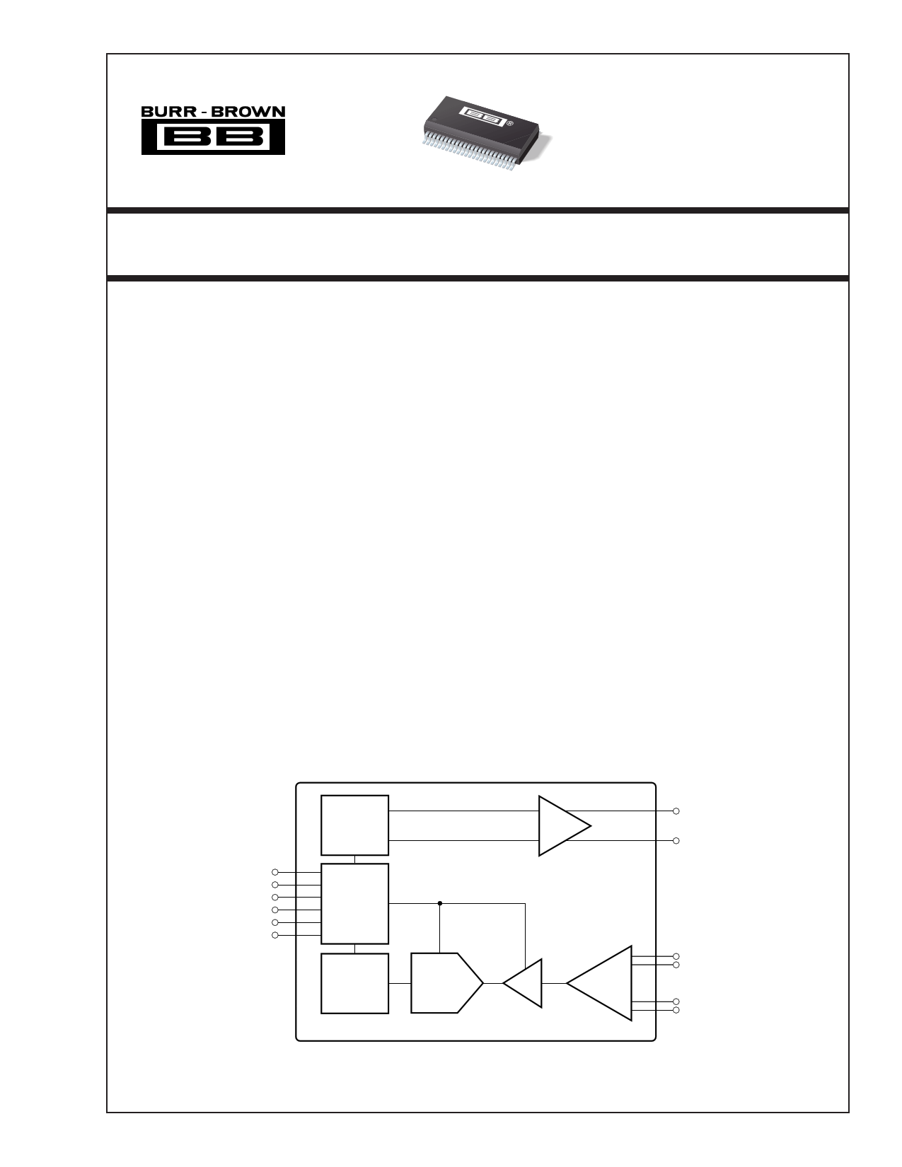
Functionally, each half of this unit consists of a transmit
and a receive section. The transmit section generates
analog signals from 2-bit digital symbol data and filters
the analog signals to create 2B1Q symbols. The on-
board differential line driver provides a 13.5dBm signal
to the telephone line. The receive section filters and
digitizes the symbol data received on the telephone line.
This IC operates on a single 5V supply. The digital
circuitry in the unit can be connected to a supply from
3.3V to 5V. It is housed in a 48-lead SSOP package.
Pulse Former
Line Driver
txLINE
txLINE
tx and rx
Interface
Lines
tx and rx
Control
Registers
Decimation
Filter
1/2 of AFE2124
∆Σ
Modulator
Difference
Amplifier
rxHYB
rxHYB
Programmable
Gain Amp
rxLINE
rxLINE
Patents Pending
International Airport Industrial Park • Mailing Address: PO Box 11400, Tucson, AZ 85734 • Street Address: 6730 S. Tucson Blvd., Tucson, AZ 85706 • Tel: (520) 746-1111
Twx: 910-952-1111 • Internet: http://www.burr-brown.com/ • Cable: BBRCORP • Telex: 066-6491 • FAX: (520) 889-1510 • Immediate Product Info: (800) 548-6132
©1999 Burr-Brown Corporation
PDS-1538A
Printed in U.S.A. April, 1999
1 page 
TYPICAL PERFORMANCE CURVES
At Output of HDSL Pulse Transformer
The curves shown below are measured at the line output of the HDSL transformer. Typical at 25°C, AVDD+ = +5V, DVDD+ = +3.3V, txBaudCLK = 584kHz (E1),
unless otherwise specified.
POWER SPECTRAL DENSITY LIMIT
–20
–38dBm/Hz for T1
–40
–40dBm/Hz for E1
–60
–80dB/decade
T1
E1
–80
–100
–120
1K
196kHz
–118dBm/Hz
292kHz
for T1
–120dBm/Hz
for E1
10K 100K
1M
Frequency (Hz)
10M
CURVE 1. Upper Bound of Power Spectral Density Measured at Output of HDSL Transformer.
B = 1.07
C = 1.00
D = 0.93
0.4T 0.4T
1.25T
A = 0.01
F = –0.01
–1.2T
–0.6T 0.5T
E = 0.03
G = –0.16
CURVE 2. Transmitted Pulse Template Measured at HDSL Transformer Output.
INPUT IMPEDANCE vs BIT RATE
200
H = –0.05
14T
A = 0.01
F = –0.01
50T
150
100
T1 = 784kbps,
32kΩ
E1 = 1168kbps,
50 21kΩ
0
100 300 500 700 900
Bit Rate (kbps)
CURVE 3. Input Impedance of rxLINE and rxHYB.
1100 1300
5
AFE2124
®
5 Page 
LAYOUT
The analog front end of an HDSL system has two conflicting
requirements. It must accept and deliver moderately high
rate digital signals and it must generate, drive, and convert
precision analog signals. To achieve optimal system perfor-
mance with the AFE2124, both the digital and the analog
sections must be treated carefully in board layout design.
The power supply for the digital section of the AFE2124 can
range from 3.3V to 5V. This supply should be decoupled to
digital ground with ceramic 0.1µF capacitors placed as close
to DGND and DVDD as possible. One capacitor should be
placed between pins 7 and 8 and the second capacitor,
between pins 41 and 42. Ideally, both a digital power supply
plane and a digital ground plane should run up to and
underneath the digital pins of the AFE2124 (pins 1 through
6, and pins 43 through 48). However, DVDD may be supplied
by a wide printed circuit board (PCB) trace. A digital ground
plane underneath all digital pins is strongly recommended.
The remaining portion of the AFE2124 should be considered
analog. All AGND pins should be connected directly to a
common analog ground plane and all AVDD pins should be
connected to an analog 5V power plane. Both of these planes
should have a low impedance path to the power supply. The
analog power supply pins should be decoupled to analog
ground with ceramic 0.1µF capacitors placed as close to the
AFE2124 as possible. One 10µF tantalum capacitor should
also be used with each AFE2124 between the analog supply
and analog ground.
Ideally, all ground planes and traces and all power planes
and traces should return to the power supply connector
before being connected together (if necessary). Each ground
and power pair should be routed over each other, should not
overlap any portion of another pair, and the pairs should be
separated by a distance of at least 0.25 inch (6mm). One
exception is that the digital and analog ground planes should
be connected together underneath the AFE2124 by a small
trace.
®
11 AFE2124
11 Page | ||
| Páginas | Total 11 Páginas | |
| PDF Descargar | [ Datasheet AFE2124.PDF ] | |
Hoja de datos destacado
| Número de pieza | Descripción | Fabricantes |
| AFE2124 | Dual HDSL/SDSL ANALOG FRONT END | Burr-Brown Corporation |
| AFE2124 | Dual HDSL/SDSL Analog Front End | Texas Instruments |
| AFE2124E | Dual HDSL/SDSL ANALOG FRONT END | Burr-Brown Corporation |
| AFE2126 | Dual HDSL/SDSL ANALOG FRONT END | Burr-Brown Corporation |
| Número de pieza | Descripción | Fabricantes |
| SLA6805M | High Voltage 3 phase Motor Driver IC. |
Sanken |
| SDC1742 | 12- and 14-Bit Hybrid Synchro / Resolver-to-Digital Converters. |
Analog Devices |
|
DataSheet.es es una pagina web que funciona como un repositorio de manuales o hoja de datos de muchos de los productos más populares, |
| DataSheet.es | 2020 | Privacy Policy | Contacto | Buscar |