|
|
|
PDF CAT511 Data sheet ( Hoja de datos )
| Número de pieza | CAT511 | |
| Descripción | 8-Bit Digital POT with Independent Reference Inputs | |
| Fabricantes | Catalyst Semiconductor | |
| Logotipo | ||
Hay una vista previa y un enlace de descarga de CAT511 (archivo pdf) en la parte inferior de esta página. Total 9 Páginas | ||
|
No Preview Available !
Advanced Information
CAT511
8-Bit Digital POT with Independent Reference Inputs
FEATURES
s Output settings retained without power
s Output range includes both supply rails
s Programming voltage generated on-chip
s Serial µP interface
s Single supply operation: 2.7V-5.5V
APPLICATIONS
s Automated product calibration.
s Remote control adjustment of equipment
s Offset, gain and zero adjustments in Self-
Calibrating and Adaptive Control systems.
s Tamper-proof calibrations.
DESCRIPTION
The CAT511 is an 8-Bit Memory DAC designed as an
electronic replacement for mechanical potentiometers
and trim pots. Intended for final calibration of products
such as camcorders, fax machines and cellular tele-
phones on automated high volume production lines and
systems capable of self calibration, it is also well suited
for applications were equipment requiring periodic ad-
justment is either difficult to access or located in a
hazardous environment.
The CAT511 consists of a programmable DAC with
independent high and low reference inputs and is ca-
pable of a rail to rail output swing. Output settings, stored
non-volatile EEPROM memory, are not lost when the
device is powered down and are automatically rein-
stated when power is returned. The output can be
dithered to test new output values without effecting the
stored setting and can be read back without disturbing
the DAC’s output.
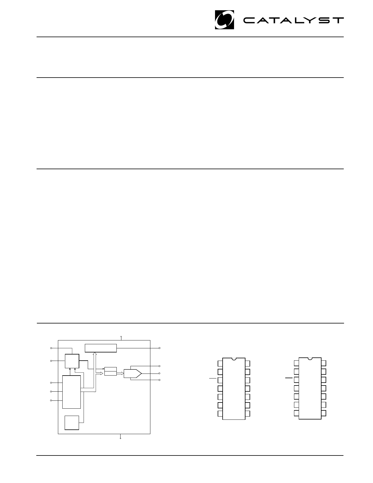
FUNCTIONAL DIAGRAM
VDD
1
RDY/BSY
3
SERIAL DATA OUTPUT
6
DO
PROG
7
PROGRAM
CONTROL
CLK
2
4
CS
5
DI
DATA
CONTROLLER
EEPROM
LATCH
DAC 1
14 VREF H1
12 VOUT 1
9 VREF L1
H.V.
CHARGE
PUMP
CAT511
8
GND
Control of the CAT511 is accomplished with a simple 3
wire serial interface. A Chip Select pin allows several
CAT511's to share a common serial interface and com-
munications back to the host controller is via a single
serial data line thanks to the CAT511’s Tri-Stated Data
Output pin. A RDY/BSYoutput working in concert with
an internal low voltage detector signals proper operation
of EEPROM Erase/Write cycle.
The CAT511 operates from a single 3–5 volt power
supply. The high voltage required for EEPROM Erase/
Write operations is generated on-chip.
The CAT511 is available in the 0°C to 70°C Commercial
and –40°C to +85°C Industrial operating temperature
ranges and offered in 14-pin plastic DIP and Surface
mount packages.
PIN CONFIGURATION
DIP Package (P)
SOIC Package (J)
VDD
CLK
RDY/BSY
CS
DI
DO
PROG
1 14
2 13
3 12
4 11
CAT511
5 10
69
78
VREF H1
NC
VOUT1
NC
NC
VREF L1
GND
VDD
CLK
RDY/BSY
CS
DI
DO
PROG
1 14
2 13
3 12
4 11
CAT511
5 10
69
78
VREF H1
NC
VOUT1
NC
NC
VREF L1
GND
© 2001 by Catalyst Semiconductor, Inc.
Characteristics subject to change without notice
1
1 page 
Advanced Information
PIN DESCRIPTION
Pin Name
Function
1 VDD
2 CLK
Power supply positive
Clock input pin
3 RDY/BSY Ready/Busy output
4 CS
Chip select
5 DI
Serial data input pin
6 DO
Serial data output pin
7 PROG
EEPROM Programming Enable
Input
8 GND
Power supply ground
9 VREFL1
Minimum DAC 1 output voltage
10 NC
No Connect
11 NC
No Connect
12 VOUT1
DAC 1 output
13 NC
No Connect
14 VREFH1
Maximum DAC 1 output voltage
CAT511
DAC addressing is as follows:
DAC OUTPUT
VOUT1
A0
0
A1
1
DEVICE OPERATION
The CAT511 is an 8-bit Digital to Analog Converter
(DAC) whose output can be programmed to any one of
256 individual voltage steps. Once programmed, the
output setting is retained in non-volatile EEPROM
memory and will not be lost when power is removed from
the chip. Upon power up the DACs return to the setting
stored in EEPROM memory. The DAC can be written to
and read from without effecting the output voltage during
the read or write cycle. The output can also be adjusted
without altering the stored output setting, which is useful
for testing a new output setting before storing in memory.
DIGITAL INTERFACE
The CAT511 employs a standard 3 wire serial control
interface consisting of Clock (CLK), Chip Select (CS)
and Data In (DI) inputs. For all operations, address and
data are shifted in LSB first. In addition, all digital data
must be preceded by a logic “1” as a start bit. The DAC
address and data are clocked into the DI pin on the
clock’s rising edge. When sending multiple blocks of
information a minimum of two clock cycles is required
between the last block sent and the next start bit.
Multiple devices may share a common input data line by
selectively activating the CS control of the desired IC.
Data Outputs (DO) can also share a common line
because the DO pin is Tri-Stated and returns to a high
impedance when not in use.
CHIP SELECT
Chip Select (CS) enables and disables the CAT511’s
read and write operations. When CS is high data may be
read to or from the chip, and the Data Output (DO) pin is
active. Data loaded into the DAC control register will
remain in effect until CS goes low. Bringing CS to a logic
low returns all DAC outputs to the settings stored in
EEPROM memory and switches DO to its high imped-
ance Tri-State mode.
Because CS functions like a reset the CS pin has been
desensitized with a 30 ns to 90 ns filter circuit to prevent
noise spikes from causing unwanted resets and the loss
of volatile data.
CLOCK
The CAT511’s clock controls both data flow in and out of
the device and EEPROM memory cell programming.
Serial data is shifted into the DI pin and out of the DO pin
on the clock’s rising edge. While it is not necessary for
the clock to be running between data transfers, the clock
must be operating in order to write to EEPROM memory,
even though the data being saved may already be
resident in the DAC control register.
No clock is necessary upon system power-up. The
CAT511’s internal power-on reset circuitry loads data
from EEPROM to the DAC without using the external
clock.
5
5 Page | ||
| Páginas | Total 9 Páginas | |
| PDF Descargar | [ Datasheet CAT511.PDF ] | |
Hoja de datos destacado
| Número de pieza | Descripción | Fabricantes |
| CAT511 | 8-Bit Digital POT with Independent Reference Inputs | Catalyst Semiconductor |
| CAT5110 | 32-tap Digital Potentiometers | ON Semiconductor |
| CAT5110 | (CAT5110 - CAT5125) Digitally Programmable Potentiometers | Catalyst Semiconductor |
| CAT5111 | 100-Tap Digitally Programmable Potentiometer | ON Semiconductor |
| Número de pieza | Descripción | Fabricantes |
| SLA6805M | High Voltage 3 phase Motor Driver IC. |
Sanken |
| SDC1742 | 12- and 14-Bit Hybrid Synchro / Resolver-to-Digital Converters. |
Analog Devices |
|
DataSheet.es es una pagina web que funciona como un repositorio de manuales o hoja de datos de muchos de los productos más populares, |
| DataSheet.es | 2020 | Privacy Policy | Contacto | Buscar |