|
|
|
PDF A8501 Data sheet ( Hoja de datos )
| Número de pieza | A8501 | |
| Descripción | 4 Channel x 100 mA WLED/RGB Driver | |
| Fabricantes | Allegro MicroSystems | |
| Logotipo | ||
Hay una vista previa y un enlace de descarga de A8501 (archivo pdf) en la parte inferior de esta página. Total 24 Páginas | ||
|
No Preview Available !
A8501
2 MHz, 4 Channel×100 mA WLED/RGB Driver
with Output Disconnect
Features and Benefits
▪ 600 kHz to 2.2 MHz switching frequency—ability to
operate above the AM band
▪ Internal bias supply for single-supply operation (VIN = 6.8 to 21 V)
▪ Boost converter with integrated 40 V DMOS switch and
OVP–load-dump protection
▪ 3.5 μA shutdown current—limits battery drain
▪ Active current sharing between LED strings for
0.8% current matching and 0.7% accuracy
▪ Drive up to 9 series LEDs in 4 parallel strings, 36 LEDs
maximum (Vf = 3.5 V, If = 100 mA)
▪ LED sinks rated for 100 mA each (400 mA total)
▪ PWM dimming with LED PWM duty cycle control
▪ 4000:1 dimming range
▪ Extensive fault mode protection schemes:
▫ Shorted LED protection against misconnected loads—
with true output disconnect
▫ Open LED disconnect protects against LED failures
▫ External thermistor sensing to limit LED temperature
▫ Output overvoltage protection (OVP): 19.5 V default can
be adjusted as high as 38 V
▫ Open Schottky and open OVP resistor protection against
external component failure
▫ Input under- and overvoltage protection (UVLO and
OVLO) against VIN variation
▫ Boost current limit, output short circuit limit,
overtemperature protection (OTP), and soft start
Package:
Not to scale
28-pin TSSOP with
exposed thermal pad
(package LP)
Description
TheA8501 is a multioutputWLED/RGB driver for backlighting
medium-size displays. The A8501 integrates a boost converter
and four 100 mA current sinks. LED channels can be tied
together for up to 400 mA sink capability. It can work from a
single power supply of 6.8 to 21 V and withstand up to 40 V.
The boost converter is a constant frequency, current-mode
converter.
Operating frequency can be set to 2 MHz in order to avoid
interference with the AM radio band. The integrated boost
DMOS switch is rated for 40 V at 3.6A. PWM dimming allows
LED currents to be controlled at up to a 1000:1 ratio.Additional
4:1 dimming can be achieved by using the DIM pin.
TheA8501 provides protection against output connector shorts
through an integrated output disconnect switch. An optional
external thermistor can be used to limit LED current based on
panel temperature.
The device is supplied in a surface mount, 28-pin TSSOP
package (suffix LP), with exposed thermal pad for enhanced
thermal dissipation. It is lead (Pb) free, with a leadframe
plating choice of 100% matte-tin (suffix T) or tin-bismuth
(suffix B).
Applications include:
▪ GPS navigation systems
▪ Automotive infotainment
▪ Back-up camera displays
▪ Cluster backlighting
▪ Portable DVD players
▪ Industrial LCD displays
Typical Application
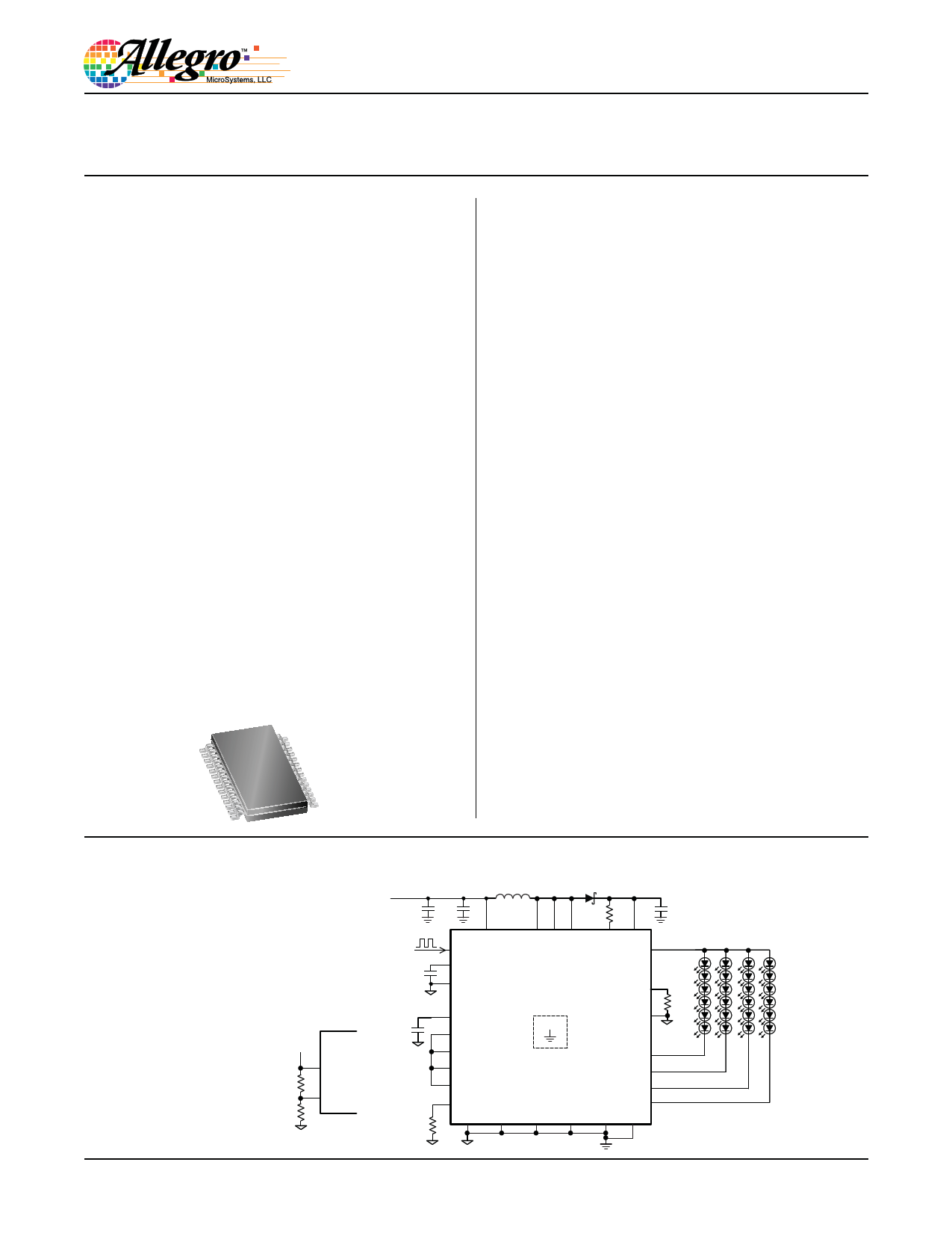
Figure 1. LCD monitor backlight driving
4 LED strings. On/off and dimming
control using ENABLE pin.
• Current = 50 mA per string
• OVP = 35 V nominal
• Switching frequency = 2 MHz
8501-DS, Rev.4
A8501
RVC
NTC
VTO
VTI
–t°
Optional Configuration
for Thermal Derating
VBAT
CBAT
4.7 μF
35 V
CCOMP
1 μF
10 V
CBIAS
0.1 μF
10 V
RISET
24.3 kΩ
D1
CIN
L1
10 μH
ROVP
78.7 kΩ
COUT
4.7 μF
50 V
VIN SW SW SW OVP CAP
EN OUT
COMP
DIM
RFSET
25.5 kΩ
FSET
A8501
BIAS
SEL2
PAD
NC
SEL1
VTO
LED1
LED2
VTI LED3
ISET
LED4
AGND PGND PGND PGND LGND DGND
1 page 
A8501
2 MHz, 4 Channel×100 mA WLED/RGB Driver
with Output Disconnect
ELECTRICAL CHARACTERISTICS Valid using circuit shown in figure 1; VIN = 12 V, EN = SEL1 = SEL2 =5 V, RISET = 12.4 kΩ,
RFSET = 24.3 kΩ, VTO shorted to VTI guaranteed over the full operating temperature range with TA =TJ, typical specifications are at
TA = 25ºC; unless otherwise noted
Characteristics
Symbol
Test Conditions
Min. Typ. Max.
Unit
General
Input Voltage Range
Undervoltage Lockout Threshold
UVLO Hysteresis Window
Overvoltage Lockout Threshold
VIN
VUVLO(th)
VUVLO(hys)
VOVLO(th)
VIN falling
VIN rising
2 MHz switching at no load
8 – 21
5.7 6.5 6.8
0.21 0.55 0.81
29 32 34
4 11 15
V
V
V
V
mA
Supply Current
IS
Logic Input levels (DIM, EN, SELx Pins)
EN = VIL, in shutdown, TA = 25°C,
CAP = VIN = SW = OVP = 16 V
IS = IVIN + ISW + ICAP + IOVP
EN = VIL, in shutdown, TA = –40°C to 125°C,
CAP = VIN = SW = OVP = 16 V,
IS = IVIN + ISW + ICAP + IOVP
EN = VIL, not in shutdown, IS = IVIN
– 3.5 6
μA
– 3.5 10
μA
– 2 4 mA
Input Voltage Level-Low
Input Voltage Level-High
Input Leakage Current (EN, DIM pins)
Input Leakage Current (SELx pins)
Overvoltage Protection
VIL
VIH
Ilkg1 VDIM, VEN = 5 V
Ilkg2 VSELx = 5 V
– – 0.4
1.5 –
–
30 50 70
––1
V
V
μA
μA
Output Overvoltage Threshold
OVP Sense Current
OVP Leakage Current
Boost Switch
VOVP(th)
IOVPH
IOVP(lkg)
OVP pin connected to OUT pin
VOVP = 18 V, EN = VIL, in shutdown
18 19.5 21
183 200 217
– 0.1 1
V
μA
μA
Switch On Resistance
Switch Leakage Current
Switch Current Limit
LED Current Sinks
RSWDS(on)
ISW(lkg)
ISW(lim)
ISW = 2 A
VSW = 21 V
40 100 300 mΩ
– 0.1 10
μA
3 3.6 5.3
A
LEDx Regulation Voltage
IISET to ILEDx Current Gain
ISET Pin Voltage
VTO Pin Voltage
VTO Pin Current Maximum
VTI Pin Voltage
VLED
AISET
VISET
VTO
ITO(max)
VTI(falling)
VTI(rising)
VLED1 = VLED2 = VLED3 = VLED4
IISET = 100 μA, DIM = VIL
IISET = 100 μA, DIM= VIH
IVTO = 1 mA
IVTO increased until VTO drops by 1%
VTI start >1.34 V, VTI pin voltage decreasing
before control changes to VTI pin
VTI start <1 V VTI pin increasing before
changing to internal reference
– 750 1100
914 960 1008
228 240 252
1.13 1.235 1.34
2.00 2.46 2.65
1.5 2.4
5
1.00 1.12 1.23
1.13 1.235 1.34
mV
A/A
A/A
V
V
mA
V
V
ISET Pin Allowable Current Range
IISET
20 – 100 μA
Continued on the next page…
Allegro MicroSystems, LLC
115 Northeast Cutoff
Worcester, Massachusetts 01615-0036 U.S.A.
1.508.853.5000; www.allegromicro.com
5
5 Page 
A8501
2 MHz, 4 Channel×100 mA WLED/RGB Driver
with Output Disconnect
Performance Characteristics
Output LED Open Protection
VBAT= 12 V, ILED = 100 mA per LED string, EN = high
LED string #1 disconnected. VOUT increases to OVP level, and LED string #1 is
removed from regulation. The rest of the LED strings continue to function normally.
VBAT
C1
VOUT
C2 VLED1
C3
IOUT
C4
Symbol
C1
C2
C3
C4
t
Parameter
VBAT
VOUT
VLED1
IOUT
time
Units/Division
10 V
20 V
1V
500 mA
100 μs
t
All four LED strings disconnected simultaneously. VOUT increases to OVP
level, and all LED strings are removed from regulation.
VBAT
C1
VOUT
C2 VLED1
C3
IOUT
C4
t
Symbol
C1
C2
C3
C4
t
Parameter
VBAT
VOUT
VLED1
IOUT
time
Units/Division
10 V
20 V
1V
500 mA
100 μs
Allegro MicroSystems, LLC
115 Northeast Cutoff
Worcester, Massachusetts 01615-0036 U.S.A.
1.508.853.5000; www.allegromicro.com
11
11 Page | ||
| Páginas | Total 24 Páginas | |
| PDF Descargar | [ Datasheet A8501.PDF ] | |
Hoja de datos destacado
| Número de pieza | Descripción | Fabricantes |
| A8500 | Flexible WLED/RGB Backlight Driver | Allegro MicroSystems |
| A8501 | 4 Channel x 100 mA WLED/RGB Driver | Allegro MicroSystems |
| A8501 | PWM CONTROL STEP-UP DC-DC CONVERTER | AiT Semiconductor |
| Número de pieza | Descripción | Fabricantes |
| SLA6805M | High Voltage 3 phase Motor Driver IC. |
Sanken |
| SDC1742 | 12- and 14-Bit Hybrid Synchro / Resolver-to-Digital Converters. |
Analog Devices |
|
DataSheet.es es una pagina web que funciona como un repositorio de manuales o hoja de datos de muchos de los productos más populares, |
| DataSheet.es | 2020 | Privacy Policy | Contacto | Buscar |