|
|
|
PDF CAT5251 Data sheet ( Hoja de datos )
| Número de pieza | CAT5251 | |
| Descripción | Quad Digital Potentiometer | |
| Fabricantes | ON Semiconductor | |
| Logotipo | ||
Hay una vista previa y un enlace de descarga de CAT5251 (archivo pdf) en la parte inferior de esta página. Total 15 Páginas | ||
|
No Preview Available !
CAT5251
Quad Digital
Potentiometer (POT)
with 256 Taps
and SPI Interface
Description
The CAT5251 is four digital POTs integrated with control logic and
16 bytes of NVRAM memory. Each digital POT consists of a series of
resistive elements connected between two externally accessible end
points. The tap points between each resistive element are connected to
the wiper outputs with CMOS switches. A separate 8-bit control
register (WCR) independently controls the wiper tap switches for each
digital POT. Associated with each wiper control register are four 8-bit
non-volatile memory data registers (DR) used for storing up to four
wiper settings. Writing to the wiper control register or any of the
non-volatile data registers is via a SPI serial bus. On power-up, the
contents of the first data register (DR0) for each of the four
potentiometers is automatically loaded into its respective wiper
control register.
The CAT5251 can be used as a potentiometer or as a two terminal,
variable resistor. It is intended for circuit level or system level
adjustments in a wide variety of applications. It is available in the
−40C to 85C industrial operating temperature range and offered in a
24-lead SOIC and TSSOP package.
Features
Four Linear-taper Digital Potentiometers
254 Resistor Taps per Potentiometer
End to End Resistance 50 kW or 100 kW
Potentiometer Control and Memory Access via SPI Interface
Low Wiper Resistance, Typically 100 W
Nonvolatile Memory Storage for up to Four Wiper Settings for Each
Potentiometer
Automatic Recall of Saved Wiper Settings at Power Up
2.5 to 6.0 Volt Operation
Standby Current less than 1 mA
1,000,000 Nonvolatile WRITE Cycles
100 Year Nonvolatile Memory Data Retention
SOIC 24-lead and TSSOP 24-lead
Industrial Temperature Range
These Devices are Pb-Free, Halogen Free/BFR Free and are RoHS
Compliant
http://onsemi.com
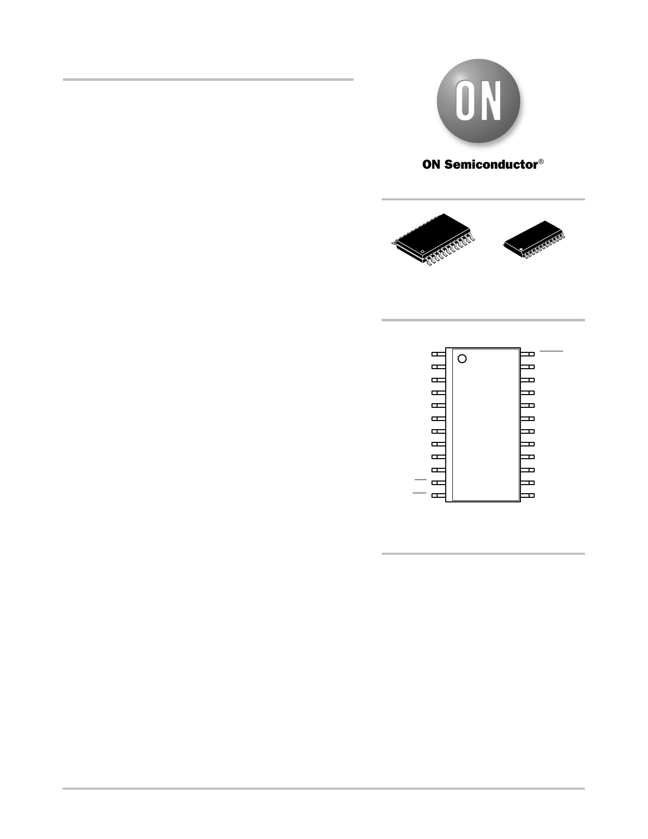
TSSOP−24
Y SUFFIX
CASE 948AR
SOIC−24
W SUFFIX
CASE 751BK
PIN CONNECTIONS
SO
A0
RW3
RH3
RL3
NC
VCC
RL0
RH0
RW0
CS
WP
1
CAT5251
SOIC−24 (W)
TSSOP−24 (Y)
(Top View)
HOLD
SCK
RL2
RH2
RW2
NC
GND
RW1
RH1
RL1
A1
SI
ORDERING INFORMATION
See detailed ordering and shipping information in the package
dimensions section on page 13 of this data sheet.
Semiconductor Components Industries, LLC, 2013
July, 2013 − Rev. 9
1
Publication Order Number:
CAT5251/D
1 page 
CAT5251
Table 4. POTENTIOMETER CHARACTERISTICS (Over recommended operating conditions unless otherwise stated.)
Symbol
Parameter
Test Conditions
Min Typ Max Units
RPOT
RPOT
Potentiometer Resistance (−00)
Potentiometer Resistance (−50)
Potentiometer Resistance Tolerance
100 kW
50 kW
20 %
RPOT Matching
Power Rating
25C, each pot
1%
50 mW
IW Wiper Current
RW Wiper Resistance
VTERM
VN
Voltage on any RH or RL Pin
Noise
Resolution
3 mA
IW = 3 mA @ VCC = 3 V
IW = 3 mA @ VCC = 5 V
200 300 W
100 150 W
VSS = 0 V
GND
VCC
V
(Note 3)
nV/Hz
0.4 %
Absolute Linearity (Note 4)
RW(n)(actual) − R(n)(expected)
(Note 7)
1 LSB
(Note 6)
Relative Linearity (Note 5)
RW(n+1) − [RW(n)+LSB]
(Note 7)
0.5 LSB
(Note 6)
TCRPOT Temperature Coefficient of RPOT
(Note 3)
300
ppm/C
TCRATIO Ratiometric Temp. Coefficient
(Note 3)
20 ppm/C
CH/CL/CW Potentiometer Capacitances
(Note 3)
10/10/25
pF
fc Frequency Response
RPOT = 50 kW (Note 3)
0.4 MHz
3. This parameter is tested initially and after a design or process change that affects the parameter.
4. Absolute linearity is utilized to determine actual wiper voltage versus expected voltage as determined by wiper position when used as a
potentiometer.
5. Relative linearity is utilized to determine the actual change in voltage between two successive tap positions when used as a potentiometer.
It is a measure of the error in step size.
6. LSB = RTOT / 255 or (RH − RL) / 255, single pot
7. n = 0, 1, 2, ..., 255.
Table 5. D.C. OPERATING CHARACTERISTICS (Over recommended operating conditions unless otherwise stated.)
Symbol
Parameter
Test Conditions
Min Typ
Max
ICC1
Power Supply Current
fSCK = 2.5 MHz, SO Open
VCC = 6 V Inputs = GND
1
ICC2
Power Supply Current
Non-volatile Write
fSCK = 2.5 MHz, SO = Open
VCC = 6 V Inputs = GND
5
ISB
ILI
ILO
VIL
VIH
VOL1
VOH1
Standby Current (VCC = 5.0 V)
Input Leakage Current
Output Leakage Current
Input Low Voltage
Input High Voltage
Output Low Voltage (VCC = 3 V)
Output High Voltage (VCC = 6 V)
VIN = GND or VCC; SO Open
VIN = GND to VCC
VOUT = GND to VCC
IOL = 3 mA
IOH = −1.6 mA
−1
VCC x 0.7
VCC − 0.8
1
10
10
VCC x 0.3
VCC + 1.0
0.4
Units
mA
mA
mA
mA
mA
V
V
V
V
Table 6. PIN CAPACITANCE (Note 8)
(Applicable over recommended operating range from TA = 25C, f = 1.0 MHz, VCC = +5.0 V (unless otherwise noted).)
Symbol
Parameter
Test Conditions Min Typ Max
COUT
CIN
Output Capacitance (SO)
Input Capacitance (CS, SCK, SI, WP, HOLD, A0, A1
VOUT = 0 V
VIN = 0 V
8
6
Units
pF
pF
http://onsemi.com
5
5 Page 
CAT5251
INSTRUCTION FORMAT
Table 14. READ WIPER CONTROL REGISTER (WCR)
CS DEVICE ADDRESSES
INSTRUCTION
DATA
CS
0 1 0 1 0 0 A1 A0 1 0 0 1 0 0 P1 P0 7 6 5 4 3 2 1 0
Table 15. WRITE WIPER CONTROL REGISTER (WCR)
CS DEVICE ADDRESSES
INSTRUCTION
DATA
CS
0 1 0 1 0 0 A1 A0 1 0 1 0 0 0 P1 P0 7 6 5 4 3 2 1 0
Table 16. READ DATA REGISTER (DR)
CS DEVICE ADDRESSES
INSTRUCTION
DATA
CS
0 1 0 1 0 0 A1 A0 1 0 1 1 R1 R0 P1 P0 7 6 5 4 3 2 1 0
Table 17. WRITE DATA REGISTER (DR)
CS DEVICE ADDRESSES
INSTRUCTION
DATA
CS
0 1 0 1 0 0 A1 A0 1 1 0 0 R1 R0 P1 P0 7 6 5 4 3 2 1 0
High
Voltage
Write
Cycle
Table 18. READ STATUS (WIP)
CS DEVICE ADDRESSES
0 1 0 1 0 0 A1 A0
0
INSTRUCTION
101 0 0
0
DATA
CS
1 7654321W
0000000I
P
Table 19. GLOBAL TRANSFER DATA REGISTER (DR)
TO WIPER CONTROL REGISTER (WCR)
CS DEVICE ADDRESSES
INSTRUCTION
0 1 0 1 0 0 A1 A0 0 0 0 1 R1 R0
0
CS
0
Table 20. GLOBAL TRANSFER WIPER CONTROL REGISTER (WCR)
TO DATA REGISTER (DR)
CS DEVICE ADDRESSES
INSTRUCTION
0 1 0 1 0 0 A1 A0 1 0 0 0 R1 R0 0 0
CS
High
Voltage
Write
Cycle
http://onsemi.com
11
11 Page | ||
| Páginas | Total 15 Páginas | |
| PDF Descargar | [ Datasheet CAT5251.PDF ] | |
Hoja de datos destacado
| Número de pieza | Descripción | Fabricantes |
| CAT525 | Configured Digitally Programmable Potentiometer (DPP): Programmable Voltage Applications | Catalyst Semiconductor |
| CAT5251 | Quad Digital Potentiometer | ON Semiconductor |
| CAT5251 | Quad Digitally Programmable Potentiometer | Catalyst Semiconductor |
| CAT5259 | Quad Digital Potentiometer | ON Semiconductor |
| Número de pieza | Descripción | Fabricantes |
| SLA6805M | High Voltage 3 phase Motor Driver IC. |
Sanken |
| SDC1742 | 12- and 14-Bit Hybrid Synchro / Resolver-to-Digital Converters. |
Analog Devices |
|
DataSheet.es es una pagina web que funciona como un repositorio de manuales o hoja de datos de muchos de los productos más populares, |
| DataSheet.es | 2020 | Privacy Policy | Contacto | Buscar |