|
|
|
PDF PE4314 Data sheet ( Hoja de datos )
| Número de pieza | PE4314 | |
| Descripción | RF Digital Step Attenuator | |
| Fabricantes | Peregrine Semiconductor | |
| Logotipo | ||
Hay una vista previa y un enlace de descarga de PE4314 (archivo pdf) en la parte inferior de esta página. Total 27 Páginas | ||
|
No Preview Available !
PE4314
Document Category: Product Specification
UltraCMOS® RF Digital Step Attenuator, 1 MHz–2.5 GHz
Features
• Attenuation step of 0.5 dB up to 31.5 dB
• Glitch-less attenuation state transitions
• Low distortion for CATV and multi-carrier applica-
tions
• Extended +105 °C operating temperature
• Parallel and Serial programming interfaces
• Packaging – 20-lead 4 × 4 × 0.85 mm QFN
Applications
• DOCSIS 3.1/0 customer premises equipment
(CPE) and infrastructure
• Satellite CPE and infrastructure
• Fiber CPE and infrastructure
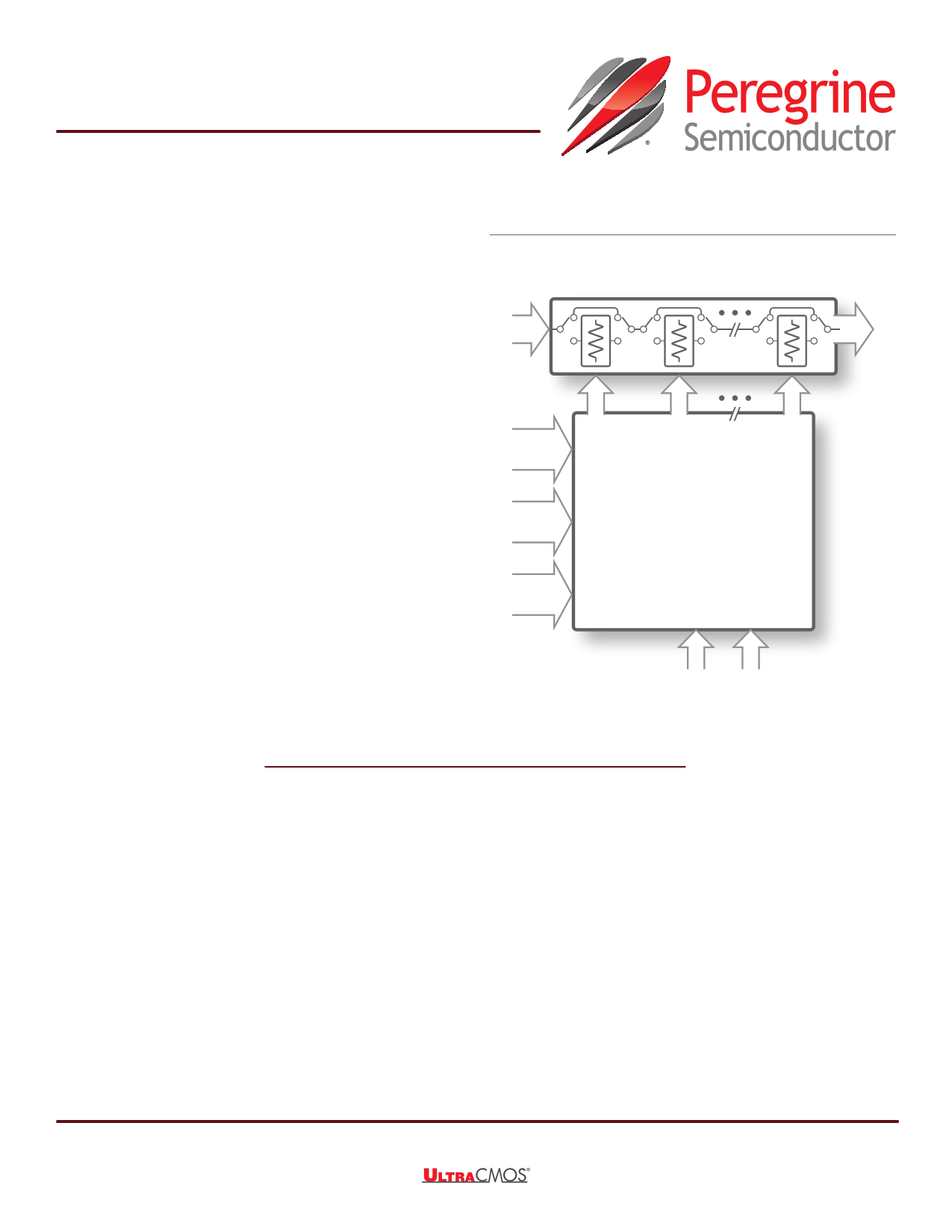
Figure 1 • PE4314 Functional Diagram
Switched Attenuator Array
RF
Input
Parallel
Control
6-bit
Serial
Control
3-bit
Power-up
Control
2-bit
Control Logic Interface
RF
Output
P/S VSS_EXT
(optional)
Product Description
The PE4314 is a 75Ω HaRP™ technology-enhanced, 6-bit RF digital step attenuator (DSA) that supports a
frequency range from 1 MHz to 2.5 GHz. It features glitch-less attenuation state transitions and supports 1.8V
control voltage and an extended operating temperature range up to +105 °C, making this device ideal for
multiple wired broadband applications.
The PE4314 is a pin-compatible upgraded version of the PE4304, PE4307, PE4308 and PE43404. An
integrated digital control interface supports both Serial and Parallel programming of the attenuation, including
the capability to program an initial attenuation state at power up.
The PE4314 covers a 31.5 dB attenuation range in a 0.5 dB step. It is capable of maintaining 0.5 dB monoto-
nicity through 2.5 GHz. In addition, no external blocking capacitors are required if 0 VDC is present on the RF
ports.
The PE4314 is manufactured on Peregrine’s UltraCMOS® process, a patented variation of silicon-on-insulator
(SOI) technology on a sapphire substrate.
©2015–2016, Peregrine Semiconductor Corporation. All rights reserved. • Headquarters: 9380 Carroll Park Drive, San Diego, CA, 92121
Product Specification
www.psemi.com
DOC-67244-4 – (03/2016)
1 page 
PE4314
RF Digital Step Attenuator
Table 3 • PE4314 Electrical Specifications (Cont.)
Parameter
Condition
Frequency Min
Typ
Max
Input IP3
Two tones at +15 dBm
10 kHz spacing
0 dB and 31.5 dB attenua-
tion states
5 MHz
10 MHz
17 MHz
35 MHz
500 MHz
1000 MHz
1900 MHz
2500 MHz
0 dB
57
69
63
62
62
59
60
58
31.5 dB
62
61
62
61
62
55
55
57
Video feed-through
DC measurement
7
Settling time
50% CTRL to 0.05 dB of
final value
1.8
Settling time
50% CTRL to 0.5 dB of final
value
0.4
Switching time
50% CTRL to 90% or 10%
RF
370 700
Attenuation transient
(envelope)
250 MHz
0.5
Notes:
1) Normal mode: connect VSS_EXT (pin 12) to GND (VSS_EXT = 0V) to enable internal negative voltage generator.
2) Bypass mode: use VSS_EXT (pin 12) to bypass and disable internal negative voltage generator.
3) The input 0.1dB compression point is a linearity figure of merit. Refer to Table 2 for the operating RF input power (75Ω).
Unit
dBm
dBm
dBm
dBm
dBm
dBm
dBm
dBm
mVPP
µs
µs
ns
dB
DOC-67244-4 – (03/2016)
www.psemi.com
Page 5
5 Page 
PE4314
RF Digital Step Attenuator
Figure 7 • Input Return Loss vs Attenuation Setting
0 dB
0.5 dB
0
-10
-20
-30
-40
-50
-60
0
0.5
1 dB
2 dB
4 dB
8 dB
1 1.5 2
Frequency (GHz)
16 dB
2.5
31.5 dB
3
Figure 8 • Output Return Loss vs Attenuation Setting
0 dB
0
0.5 dB
-10
-20
-30
-40
-50
-60
-70
0
0.5
1 dB
2 dB
4 dB
8 dB
1 1.5
Frequency (GHz)
2
16 dB
2.5
31.5 dB
3
DOC-67244-4 – (03/2016)
www.psemi.com
Page 11
11 Page | ||
| Páginas | Total 27 Páginas | |
| PDF Descargar | [ Datasheet PE4314.PDF ] | |
Hoja de datos destacado
| Número de pieza | Descripción | Fabricantes |
| PE4312 | RF Digital Step Attenuator | Peregrine Semiconductor |
| PE4314 | RF Digital Step Attenuator | Peregrine Semiconductor |
| Número de pieza | Descripción | Fabricantes |
| SLA6805M | High Voltage 3 phase Motor Driver IC. |
Sanken |
| SDC1742 | 12- and 14-Bit Hybrid Synchro / Resolver-to-Digital Converters. |
Analog Devices |
|
DataSheet.es es una pagina web que funciona como un repositorio de manuales o hoja de datos de muchos de los productos más populares, |
| DataSheet.es | 2020 | Privacy Policy | Contacto | Buscar |